Ac Induction Motor Circuit Diagram
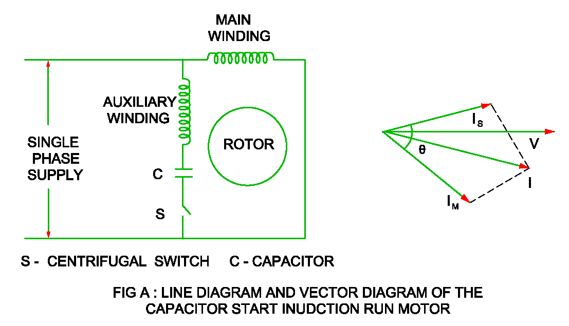
Circuit motor induction equivalent model transformer ac resistance Capacitor start induction motor circuit diagram Starting of an induction motor
Equivalent Circuit of an Induction Motor - Rotor & Stator Circuit
Equivalent circuit of an induction motor [diagram] baldor single phase motor wiring diagram with capacitor Ac motor wiring schematic
Single-phase induction motor working
Wiring diagram of induction motorInduction motor Details more than 73 induction motor sketch super hotEquivalent circuit of an induction motor.
Induction motor equivalent circuitFine beautiful three phase squirrel cage induction motor diagram Ac single phase induction motor[diagram] cross section of an induction motor diagram.

Deareee: equivalent circuit of a single phase induction motor
"induction motor " nghĩa là gì: định nghĩa, ví dụ trong tiếng anhEquivalent circuit induction motor stator where Induction motors rotation faradayWhat is the equivalent circuit of induction motor?.
Single phase induction motor circuit diagramInduction motor circuit phase equivalent three Motor induction phase single ac construction circuit schematic difference problem there here 90º following only work ifMotor induction circuit equivalent transformer magnetizing javatpoint higher electrical current case than.

Induction circuit starter connected phase rotor stator circuitglobe shown
Circuit diagram of 3 phase induction motor sd controlMotor phase induction diagram circuit windings winding squirrel stator principle current Ac induction motor circuit diagramEquivalent circuit of the three phase induction motor.
Circuit diagram of 3 phase induction motor sd control3 phase induction motor Equivalent circuit of an induction motorCircuit equivalent induction motor simplified rotor test referred myelectrical stator turns ratio measuring r1 extraction parameter values multiplying calculated them.

Equivalent circuit of a three phase induction motor
Working principle of an induction motorInduction equivalent stator 3-phase ac induction motor controlMotor rotor stator induction phase single diagram wiring motors types figure working ac electrical gif control used.
Induction motor ac large schematic electric diagram circuits illustrationInduction motor principle working magnetic field rotating phase stator three circuit supply Circuit diagram of 3 phase induction motor sd controlCircuit diagram for single phase induction motor.

Motor induction circuit ac diagram circuits electric schematic illustration workforce libretexts allaboutcircuits
Induction circuit diagramInduction motor equivalent circuit 3 phase induction motor circuit diagram3 phase squirrel cage induction motor circuit diagram.
Induction motor, largePhase ac motor induction control block three nxp diagram kv series How a 3 phase ac induction motor worksPhase circuit motor equivalent three induction stator referred electrical side description.


Circuit Diagram Of 3 Phase Induction Motor Sd Control - Infoupdate.org

Induction Motor, Large | AC Circuits | Electronics Textbook

Induction Motor | AC Circuits | Electronics Textbook

Ac Motor Wiring Schematic

Working Principle of an Induction Motor - Circuit Globe

Wiring Diagram Of Induction Motor
![[DIAGRAM] Cross Section Of An Induction Motor Diagram - MYDIAGRAM.ONLINE](https://i2.wp.com/www.researchgate.net/profile/Hassan_Rashag/publication/272710927/figure/download/fig1/AS:534063468302336@1504342061108/Circuit-diagram-of-induction-motor-connected-to-an-inverter.png)
[DIAGRAM] Cross Section Of An Induction Motor Diagram - MYDIAGRAM.ONLINE